- 您现在的位置:买卖IC网 > Sheet目录100 > NHD-0420H1Z-FSW-GBW-33V3 (Newhaven Display Intl)LCD MOD CHAR 4X20 GRY TRANSF STN
[4] �
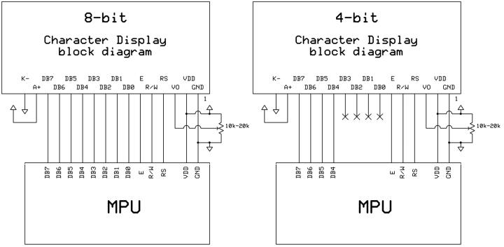
� Pin Description and Wiring Diagram �
� Pin No.�
� Symbol�
� External �
� Connection �
� Function Description�
� 1�
� Vss�
� Power Supply�
� Ground�
� 2�
� VDD�
� Power Supply�
� Supply voltage for logic (�
� +3.�
� 3V)�
� 3�
� V0�
� Power Supply�
� Powe�
� r supply for contrast (approx. �
� 0.1�
� V)�
� 4�
� RS�
� MPU�
� Register select signal. RS=0: Command, RS=1: Data�
� 5�
� R/W�
� MPU�
� Read/Write �
� select signal, R/W=1: Read R/W:=0: Write�
� 6�
� E�
� MPU�
� Operation enable signal. Falling edge triggered.�
� 7-10�
� DB0�
� -DB3�
� MPU�
� Fo�
� ur low order bi�
� -directional three�
� -state data bus lines. These four �
� are not used during 4-bit operation. �
� 11�
� -14�
� DB4�
� -DB7�
� MPU�
� Four high �
� order bi�
� -directional three�
� -state data bus lines.�
� 15�
� LED+�
� Power Supply�
� Power supply for LED Backlight (+�
� 3.3V�
� )�
� 16�
� LED�
� -�
� Power Supply�
� Ground for backlight�
� Recommended LCD connector: �
� 2.54mm pitch pins �
� Backlight connector:�
� --- �
� Mates with: �
� ---�
�  �
�
� � �  �
�
� � 发布紧急采购,3分钟左右您将得到回复。
相关PDF资料
NHD-0420H1Z-FSW-GBW-3V3
LCD MOD CHAR 4X20 WH TRANSFL
NHD-0420Z-RN-GBW
LCD MOD CHAR 4X20 NO REFL
NHD-0440AZ-FL-GBW
LCD MOD CHAR 4X40 Y/G TRANSFL
NHD-0440AZ-FL-YBW
LCD MOD CHAR 4X40 Y/G TRANSFL
NHD-0440AZ-FSW-FBW
LCD MOD CHAR 4X40 WH TRANSFL
NHD-0440AZ-NLY-FBW
LCD MOD CHAR 4X40 Y/G TRANSM
NHD-0440AZ-RN-FBW
LCD MOD CHAR 4X40 REFL
NHD-0440WH-ATFH-JT#
LCD MOD CHAR 4X40 WH TRANSFL
相关代理商/技术参数
NHD-0420H1Z-FSW-GBW-3V3
功能描述:LCD字符显示模块与配件 STN-Gray Transfl 66.0 x 36.0 RoHS:否 制造商:Lumex 显示模式:Transflective 字符计数 x 行:16 x 2 特点: 流体类型:STN 接口: 背景色: 工作温度范围:- 20 C to + 70 C 封装:Bulk
NHD-0420Z-FL-YBW-3V0
功能描述:LCD MOD CHAR 4X20 Y/G TRANSFL RoHS:是 类别:光电元件 >> 显示器模块 - LCD,OLED 字符和数字 系列:- 产品培训模块:NHDev LCD Development Board 产品变化通告:LCD Modules 3.0V Obsolescence 3/Nov/2011 标准包装:50 系列:NHD-0416B1Z-F 显示器类型:STN - 超扭转向列 显示模式:穿透/反射式 数字/字母数:64 外形L x W x H:87.00mm x 60.00mm x 14.00mm 可视范围:61.80mm L x 25.20mm W 背光:LED - 绿 显示格式:16 x 4 字符尺寸:4.75mm H x 2.95mm W 字符格式:5 x 8 点 电源电压:5.0V 点尺寸:0.55mm W x 0.55mm H 接口:- 工作温度:-20°C ~ 70°C
NHD-0420Z-RN-GBS
功能描述:LCD字符显示模块与配件 4 x 20 STN-GRAY 86.0 x 39.6 RoHS:否 制造商:Lumex 显示模式:Transflective 字符计数 x 行:16 x 2 特点: 流体类型:STN 接口: 背景色: 工作温度范围:- 20 C to + 70 C 封装:Bulk
NHD-0420Z-RN-GBW
功能描述:LCD字符显示模块与配件 STN- GRAY Refl 86.0 x 39.6 RoHS:否 制造商:Lumex 显示模式:Transflective 字符计数 x 行:16 x 2 特点: 流体类型:STN 接口: 背景色: 工作温度范围:- 20 C to + 70 C 封装:Bulk
NHD-0440AZ-FL-GBW
功能描述:LCD字符显示模块与配件 4 x 40 STN-GRAY 190.0 x 54.0 RoHS:否 制造商:Lumex 显示模式:Transflective 字符计数 x 行:16 x 2 特点: 流体类型:STN 接口: 背景色: 工作温度范围:- 20 C to + 70 C 封装:Bulk
NHD-0440AZ-FL-YBW
功能描述:LCD字符显示模块与配件 STN- Y/G Transfl 190.0 x 54.0 RoHS:否 制造商:Lumex 显示模式:Transflective 字符计数 x 行:16 x 2 特点: 流体类型:STN 接口: 背景色: 工作温度范围:- 20 C to + 70 C 封装:Bulk
NHD-0440AZ-FL-YBW-E
制造商:Newhaven Display International 功能描述:
NHD-0440AZ-FSW-FBW
功能描述:LCD字符显示模块与配件 4 x 40 FSTN(+) 190.0 x 54.0 RoHS:否 制造商:Lumex 显示模式:Transflective 字符计数 x 行:16 x 2 特点: 流体类型:STN 接口: 背景色: 工作温度范围:- 20 C to + 70 C 封装:Bulk